Today, many are wondering how and what is the best way to heat their home if there is no gas. Firewood and coal are among the most affordable types of fuel. Therefore, the right solution here would be to build a heating stove, or even better, add a cooking stove function to it. There are a lot of design options both in form and in operating principles.
In this article I will introduce you to the features of the Kuznetsov furnace, its advantages and a step-by-step scheme for constructing such a unit yourself.
Application of the Kuznetsov furnace
Over many years of inventive activity, I.V. Kuznetsov has developed about 150 models of furnaces, designed for use in all areas of human activity without exception where heat generation is required. According to the type of specialization, “blacksmithing” is:
- heating;
- cooking;
- heating and cooking;
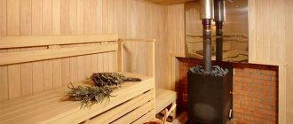
- baths
- outdoor, intended for smoking food, barbecuing and grilling;
- fireplaces with an open firebox, allowing you to admire the flames.
Examples of the Kuznetsov furnace
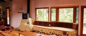
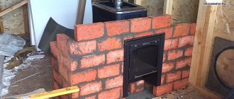
Heating and cooking option
Heating and cooking stove
Complex units are popular due to their expanded functionality. Despite multitasking, such devices work on the principle of distributing hot air into different flows. The design not only has a cooking surface, but also a built-in oven for baking. You can cook and bake a short time after kindling. Above the niche where the cooking stove is located, there are shelves for drying.
The cap receives and removes gases from its lower part. If you leave the valve open, this will not affect the heating performance, since the air remains in the cavity for a long time and releases energy. Waste after combustion leaves the furnace freely. This device is effective if there is little space for a tall pipe.
Advantages and disadvantages
The wide popularity of Kuznetsov stoves and the deep respect that people knowledgeable in the stove business have for them are due to a number of advantages:
- The efficiency of “blacksmiths” exceeds 80%, and for some models it can reach 95%.
- Furnaces operate at high temperatures, but at the same time they do without materials and technologies available only in factory conditions.
- The high-temperature mode allows you to heat the stove even with the most waste and low-quality fuel.
- Again, due to the high combustion temperature, the fuel is oxidized almost completely, so soot is formed in minimal quantities. The oven may not require cleaning for several years.
- The design of the furnace ensures very uniform heat transfer between the fireboxes, while less material is used than in construction using traditional technology.
- In furnaces equipped with a heat exchanger, heat for heating water is taken from the flue gases, and not from the firebox, so the “blacksmith” can easily perform the function of a boiler without deteriorating performance.
- The operating principle of the stove provides good draft, so there is no need to build a high chimney.
- “Kuznetsovka” is very plastic both in terms of design and design. That is, it can easily be adjusted to any room without compromising performance and efficiency.
- The stove is designed in such a way that after firing, its chimney does not need to be blocked with a view. Carbon monoxide poisoning is completely excluded.
- The design assumes uniform heat distribution in the furnace body, so cracks do not develop in the masonry due to local deformations.
What can you say about the disadvantages? Technically there are none, but there are still some things to consider. The Kuznetsov furnace cannot have massive walls - this would negate many of its advantages. But at the same time it is subject to fairly high thermal loads. Therefore, this unit must be carefully calculated and verified at the development stage and built just as carefully, with scrupulous compliance with all technology requirements. At the slightest deviation from the technical regulations, the “blacksmithing” will turn out to be very short-lived.
You can even build a Russian stove with your own hands if you follow the detailed instructions. You will find them in our next article: .
DIY construction
Undertaking construction on your own is appropriate only for a person with the skills of a mason. There are many subtleties in stove construction that become clear only after many years of work. It is worth learning the main points in order to control the work of hired craftsmen and choose materials yourself.
Model selection
For construction, you can choose a model with a warm bed.
Construction begins with choosing a model. Even at the design stage, the following is determined:
- appointment;
- required heat transfer power;
- configuration;
- materials for masonry and their quantity.
The summary table on the website shows the geometric dimensions and heat transfer of each side. After going to the “free drawings” section, the amount of materials is calculated in order, accurate to the brick. For drawings of some stoves you will have to pay a small amount - registration on the site will be required to purchase.
Materials and accessories
All consumables are selected and purchased in advance, since after the start of construction you may not quickly find, for example, doors or valves of the required size.
To lay out the combustion chamber of the furnace you will need a heat-resistant brick
For the Kuznetsov furnace you will need:
- three types of bricks - solid red with a grade of at least M-150, fireclay heat-resistant, preferably ShB-8, and finishing for the outer layer of masonry;
- sand-cement mixture for stoves;
- cast products according to the drawing - doors for the combustion and ash chambers, grate, valves and views, doors for cleaning channels;
- wire for tying rows at the rate of laying along the perimeter of every two rows;
- ceiling corners for the firebox;
- reinforcing mesh for pouring the foundation;
- asbestos cord for thermal insulation of cast iron.
To work, you will need a trowel or trowel, containers for mixing solutions, a level, jointing, tape measure and a plumb line.
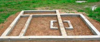
At the first stage of construction, a foundation is built, the length and width of which corresponds to the size of the furnace. To do this, make a hole in the ground, pour and compact 10–15 cm of sand. The prepared formwork is poured with heavy concrete.
The upper edge of the poured foundation is made 13–15 cm below the floor level, then the recess is filled with two layers of refractory brick. They are needed to prevent heat from escaping through the floor into the ground.
The time it takes for the foundation to gain full strength is 28 days, but laying can begin in 17–20 days if the construction is not planned to be completed very quickly.
At the next stages, the “body” of the furnace is erected, strictly following the instructions, observing the order and checking the horizontal and vertical levels.
The passage of the chimney through the ceilings is provided with thermal insulation, which prevents heating of building materials.
Immediately after completion of construction, a low-intensity test fire is made. At this time, all substances that give off an unpleasant odor burn out, and the walls warm up and dry evenly.
Design and principle of operation
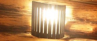
The inventor I.V. Kuznetsov used a bell-type furnace, known for its efficiency, as a basis.
This is what a bell furnace looks like - a prototype of Kuznetsov’s model
The high efficiency of such furnaces is due to the nature of the movement of flue gases. If in channel stoves they are drawn into the chimney, often without having time to give off heat to the brick mass, then in bell-type stoves they swirl under the roof of the bell for a long time until they cool down. Only then do they fall down to the outlet, from where they then enter the chimney. The bell filled with gases simultaneously plays the role of a view: cold air from the chimney cannot penetrate into it, just as water cannot fill an inverted diving bell. This effect is called gas view.
The inventor worked with a complicated version of such a furnace, which had two hoods.
Diagram of a two-bell model
Scheme of a two-bell furnace
As you can see, the hoods are connected in series, that is, heat from the flue gases is removed in a two-stage manner. Previously, the construction of stoves with such a design was not very willingly undertaken - not only because of the complexity, but also some undesirable features. So, for example, the draft in the second bell can easily break the gas plug in the first, negating the effect of the “gas view”.
The master dealt with this drawback in the following way. The furnace was equipped with so-called downstream channels, laid to bypass the heat-accumulating parts of the array. While the flame is burning in the firebox, the convective flow it creates ensures that the draft operates as usual. When the fuel is consumed and convection stops, the draft will redistribute itself in such a way that the cold air flow will follow through the downstream channels, and not through the heated body of the furnace.
This solution not only compensated for the instability of the gas coil, but also turned out to be more reliable: a plug formed by gases can be pulled out by a strong gust of wind, while in the Kuznetsov furnace, the draft is redirected away from the hot mass under any conditions. In addition, thanks to the presence of downstream channels, there is no need to arrange room ventilation.
Safety
The main requirement for any type of oven is its safety. In addition to the fact that the use of a constant open fire in the house always sharply increases the risk of fire, the combustion of any type of fuel produces carbon dioxide, which is extremely dangerous for humans, which, if the design is defective or improperly used, leads to carbon dioxide poisoning.
Therefore, if the owner of the house does not have stove construction skills, the construction of the stove should be entrusted to a master, despite the high cost of this work. Only a specialist will be able to lay bricks in the stove correctly with minimal gaps and correctly install the chimney and pipe, taking into account all possible nuances of its operation, including the prevailing wind direction.
Calculation of the Kuznetsov furnace
“Kuznetsovka” is a very complex heating device and attempts to calculate and design it yourself will not lead to anything good. You just need to choose from all the available options the most suitable one for yourself - the author does not make a secret of his developments. If the characteristics of the model you like do not indicate the heat transfer power, it can be calculated approximately: a stove that is heated twice a day, every sq. m of its surface gives off approximately 500 W of heat.
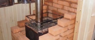
The OVIK-9 furnace, the manufacturing procedure of which we will consider, with dimensions of 1015x630x2100 mm, has a heat transfer power of 3.6 kW.
Model OVIK-9: general view
Calculation of dome heating devices
Design includes methods for selecting internal fittings and equipment to obtain effective draft and increase heat transfer without loss. The heat loss of the room is calculated by volume, then the resulting value is multiplied by 21. This is the average loss for 1 cubic meter. The stove power should exceed the value by 15%.
If the projects do not suit the user, he can make the project himself, taking as a basis the general rules for the construction of bell-shaped structures. Determines the external dimensions of the heating structure, dividing the result by 300. The number means the heat power that the square of the external wall of the stove can give off. The required square footage of the walls located above the grate is obtained.
Preparatory work
First of all, you need to choose a place to build a furnace. The easiest way to do this is before building a house - then both the stove and the building are designed together so that three or at least two rooms are heated. With a ready-made house, the situation is more complicated. In this case, they tend to build the stove into an interior partition, since installing it into a load-bearing wall requires complex calculations and dangerous, time-consuming work (part of the wall will have to be dismantled, keeping the load from being blocked by a system of lintels and columns).
You can, of course, limit yourself to a simple wall-mounted arrangement, but then only one room will be heated.
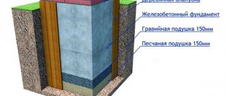
A reinforced concrete foundation must be built at the selected location. Its dimensions must exceed the dimensions of the oven by at least 100 mm on each side. It is not allowed to combine the foundation of the furnace with the foundation of the building - both structures give different settlements and one of the foundations will pull the other along with it, causing it to skew.
A reinforced concrete foundation must be installed under the furnace.
The depth of the foundation depends on the bearing capacity of the soil, the depth of its freezing, and the method of operation of the building (periodically/continuously). Typically, in buildings with year-round habitation of people located on stable ground, the foundation is deepened by 400–600 mm. Crushed stone should be poured onto the bottom of the excavation as a reinforcing layer, and a sand cushion should be placed on top of it.
Then everything is done using traditional technology - they install the formwork, fix the reinforcement frame and fill it with concrete. You should proceed to the construction of the furnace only after the concrete has fully matured and gained sufficient strength - this usually takes about a month.
Before laying the 1st row, waterproofing of two layers of roofing felt or roofing felt must be laid on top of the foundation. The contours of the future furnace are drawn on it with chalk - this will make it easier to navigate.
Correct location
The main purpose of any furnace is heating; its location must be chosen to provide heat in the most efficient way. Kuznetsov stoves are infrared heaters that provide the greatest heat through direct radiation. Thus, maximum power is achieved with the correct positioning. Therefore, the center of the room is always the right choice. A wise decision is to place it as a divider between functional spaces, such as the kitchen and living room or living room and bedroom.
Try to avoid placing the masonry stove next to an outside wall or, even worse, placing it in a niche in an outside wall (a typical location for conventional fireplaces) if you want to keep the heat inside the room.
The choice of a stove of one type or another and its location in the house, in addition to the owner’s preferences, depends on the intended purpose of the stove, the size of the house and its level of thermal insulation, the number and size of windows. In addition, for normal operation and repairs, access to the stove must be free from all sides, that is, none of the sides of the stove should simultaneously enter any of the external walls of the house.
Materials and tools
To work you will need:
- trowel;
- level;
- mallet and other construction tools.
To divide bricks you will need a pick hammer and a grinder with a diamond wheel.
This set of tools will be needed for work
The furnace will be built from two types of bricks: conventional solid ceramic with a grade of M150 (250x120x65 mm) and fireclay grade ShB-8 (250x123x65 mm) or Sh-5 (230x114x40 mm). The firebox walls will be lined with fireclay bricks.
When purchasing fireclay bricks, you should be very careful. Unscrupulous sellers may pass it off as acid-resistant brick, which is similar in appearance but cannot withstand high temperatures. So it won’t hurt to ask to see a certificate.
Brick for laying the furnace
It is often recommended to choose fireclay bricks by color - the darker the better. But this rule does not always apply. If clay taken from different deposits was used, then the characteristics of light brick may well be higher than that of dark brick. It is more correct to evaluate the quality of fireclay bricks according to the following criteria:
- the structure must be uniform and fine-grained - without pores and inclusions visible to the naked eye;
- when tapped with a metal object (light hammer or wrench), the brick should produce a clear, abrupt and ringing sound;
- when dropped, it should break into large pieces (low-quality ones crumble into small fragments down to sand).
For a structure with dimensions of 1015x630x2100 mm, you will need 430 ceramic bricks (excluding the chimney) and 22 fireclay bricks.
How to prepare the solution
The solution used is clay. The clay and sand used for its preparation should not contain organic impurities that can lead to cracking of the seams. In clay, the presence of these impurities can be recognized by a clearly audible smell (it can even be pleasant) - normally clay has almost no smell.
Sand should be used either from mountain sand or made by grinding broken bricks - in these varieties the content of organic impurities is minimal, or they are completely absent. Brick sand usually costs less than mountain sand, but is not inferior in quality. Just pay attention to the following circumstance: for ceramic masonry mortar you need sand from ceramic bricks, and for fireclay - accordingly, from fireclay.
Pay attention to the grade of clay. The mortar for fireclay masonry should be prepared on the basis of white kaolin or fireclay marl. Any clay with fire-resistant properties is suitable for ceramic masonry, for example, gray or blue Cambrian, gray kaolin.
Clay of the same grade, but from different deposits, can differ greatly in viscosity, fat content and adhesive properties. Therefore, the solution recipe, namely the optimal ratio of sand and clay in it, should be selected experimentally. In the case of using brick sand, this is done as follows:
- A 1 kg portion of clay should be filled to the top with water and left for a day.
- After this, the soggy clay is kneaded with the addition of water until it looks like plasticine or thick dough and stops sticking to your hands.
Next, the clay is divided into 5 equal portions, to each of which a certain amount of sand is added:
- first - 10% of the volume of clay;
- in the 2nd - 25%;
- in the 3rd - 50%;
- in the 4th - 75%;
- in the 5th - 100%.
Each portion must be thoroughly stirred until smooth and dried for 4 hours. Don't forget to mark how much sand is contained where.
After this, each portion of the solution must be rolled out into the shape of a cylinder 30 cm long and 1–1.5 cm in diameter. All of them are wrapped around a round blank with a diameter of about 5 cm. Now the test samples must be dried for two weeks at room temperature and without drafts .
After this, it remains to evaluate each of the options:
- If there are no cracks on the cylinder at all or they are present in the form of a very fine mesh, such a solution can be used for any part of the furnace.
- If the depth of the cracks reaches 1–2 mm, the solution can withstand temperatures up to 300 degrees. This mixture can be used for laying a country fireplace or barbecue.
- If there are deep cracks or breaks, the solution is considered unsuitable for use - the proportion of sand in it is excessive.
Typically, about 0.2 cubic meters are consumed for a laying of 500 bricks. m mixture of clay and sand.
Note! If you don’t mind the additional costs, you can purchase a ready-made mixture for preparing a stove solution at a specialized store.
Having thus determined the optimal combination of clay and sand, we begin to prepare the solution:
- the required amount of clay (approximately 40 kg per 100 bricks) is again soaked for 24 hours, kneaded until the consistency of dough, but then rubbed through a sieve with a mesh size of 3x3 mm;
- then sand is added according to the experimentally selected recipe;
- gradually adding water, stir the solution until creamy;
- evaluate how the solution wets the trowel and, if necessary, adjust its composition by adding a small amount of clay or sand.
What else do you need?
- A fire door, for example, brand DT-3, with opening dimensions of 250x210 mm.
- Blower door, for example, DPK brand, with an opening of 250x140 mm.
- Grate size 250x252 mm.
- Cast iron hob with two burners, size 586x336 mm.
- Doors measuring 510x340 mm, 2 pcs. – for the cooking chamber.
- Gate valves with a flow area of 130x130 mm, 2 pcs. – for the cooking chamber and for switching between summer and winter operating modes.
- A valve with a clearance of 250x130 mm - for a chimney.
- Equal angle pieces 36x4, 600 mm long (4 pcs.).
- A piece of steel strip 40x4 mm, 600 mm long.
- Steel sheet 3 mm thick, size 600x550 mm.
- 3 mm thick steel sheet measuring 500x700 mm to protect the floor in front of the firebox.
Replace steel with any other fireproof flooring, for example, ceramic tiles.
Have you always dreamed of having a magical fireplace in your home? You can fold it yourself. And the following guide will help with this: .
Recommendations for self-construction
If you decide to build a stove according to one of Kuznetsov’s plans with your own hands, get ready for careful and scrupulous work. On the diagrams you will find a graphic representation of each row, but before starting laying you need to become familiar with the features of the technique, in particular:
- selection and pre-processing of bricks;
- purchase of metal parts (plates, dampers, doors, valves);
- determining the most suitable location;
- preparation of the base and foundation;
- possibility of installing a chimney, etc.
Fireclay refractory brick (Sh-5, ShB-8) is recognized as the best material for the internal masonry of “smiths”, and ceramics (M-150) for external decoration. To strengthen brick walls, metal elements (rebar, wire) are used. In order for the stove to function with maximum heat output, experienced craftsmen hone not only their skills, but also every brick - literally. They polish every detail, which is why projects completed by professionals look flawless.
Fireclay brick masonry
Having the author's order in hand, we recommend not to experiment, but to follow the designated order. Deviations from the diagram do not guarantee complete heat transfer.
Masonry: ordering and step-by-step instructions
The sequence of work looks like this:
Lay out the 1st row of 20 bricks, which should be an ideal rectangle with a strictly horizontal surface.
First row diagram
“Rectangularity” is checked by measuring the diagonals - they must be equal. In the absence of experience, the row must first be laid out without mortar and only then, when everything has been adjusted and checked, the mortar must be applied. The thickness of the seams should be 5 mm.
Advice. To make the stove look more attractive, install rounded bricks in the corners. You don’t have to cut them yourself—such blocks are sold ready-made.
In the 2nd row, the first (lower) hood and the blower chamber originate. The two halves of the brick are laid without mortar and slightly pushed out. When the masonry is completed, these bricks will need to be removed, which will make it possible to clean the base of the cap from splashes of mortar and brick fragments. After cleaning, the halves are finally placed on the solution.
Second row diagram
When the 2nd row is laid out (14 bricks are required), install the blower door on it, supporting it with several bricks. The door frame must be wrapped with asbestos cord, which will act simultaneously as a seal and expansion joint. It is fixed in the brickwork by means of wire, which is placed in the seams.
It is recommended to use wire to reinforce the walls of the furnace, placing it in the seams of every second row.
Having laid out the 3rd row according to the diagram (the bricks included in it should tightly fix the blower door), proceed to laying the 4th. Here, in addition to ceramic bricks, fireclay bricks are used - we begin to lay out the side and rear walls of the firebox.
Third row diagram
The blower door is covered with hewn ceramic bricks looking outwards, and hewn fireclay bricks looking inwards. They must be separated by a thermal gap of 5 mm. It can be arranged in the following way: a spacer of corrugated cardboard is placed between the bricks - it has just the required thickness; When kindled, the cardboard will burn out and a gap will form on its own. Temperature gaps must be provided wherever fireclay bricks are adjacent to ceramic bricks.
Fourth row diagram
In row No. 5, the fireclay bricks forming the side walls of the firebox are slightly shifted so that the bricks of the 4th row located underneath them form a shelf 10–15 mm wide for the grate. The bricks should be moved apart so that there is a gap of 5 mm between them and the grating, which is necessary for the free expansion of the heated metal.
Fifth row diagram
The brick forming the front wall should be cut at an angle.
In the same row, the formation of a vertical channel connecting both caps begins.
When the row is laid out, you should install the grate in its place, filling the gap between it and the bricks with sand.
Installation of grate bars
In parallel with laying the 6th row, you need to install and fix the fire door. Direct contact of its frame with the brick is not allowed - it is necessary to lay an asbestos cord as a gasket. The door frame can be fixed with wire from below, but a more reliable element is required from above - the wire will quickly burn out. Instead, a steel strip is used.
Sixth row: installation of the combustion door
When laying row No. 7 on the side of the brick that forms the back wall of the firebox, a gap of 20–30 mm wide is left. This is the beginning of a dry weld.
Seventh row diagram
Having laid out row No. 8 according to the diagram, proceed to laying the 9th row. At this stage, a channel is formed connecting the firebox with the lower hood. Lilac color indicates bricks in the side walls of the firebox, the upper edges of which should be 10 mm below the plane of the row. An asbestos strip 10 mm thick will need to be laid on the left wall so that it is flush with the plane of the row.
Eighth row diagram
Pay attention to how the fire door is blocked: the bricks are cut at an angle to create a “lock-on” masonry.
Ninth row diagram
When laying out the 10th row, you should remember that ceramic bricks must be laid without mortar on the asbestos lining (it covers the fireclay bricks in the firebox wall).
Tenth row of order
It is necessary to make a cutout for the hob in the ceramic bricks surrounding the firebox. Its dimensions should be such that there is a temperature gap of 5 mm around the slab, that is, the bricks will need to be trimmed by about 10 mm. And in the contact area of the hob with fireclay bricks, it is necessary to leave a gap of 10 mm. These bricks, cut at an angle, are located in the front and to the right (indicated in orange).
If the slab is equipped with stiffening ribs at the bottom, it is necessary to additionally cut grooves in the brick so that the slab is supported on the brick along the entire edge. It is installed immediately after laying the row - on an asbestos cord soaked in clay solution. The gaps between the slab and bricks are filled with sand.
Near No. 11 the walls of the cooking chamber begin. A door for it is also installed here, the frame of which must be wrapped with asbestos cord. For fixation, you can again use wire.
Eleventh row diagram
Rows 12, 13 and 14 do not need comments - we simply lay them out in order.
After laying the bricks of the 15th row, the cooking chamber is covered with a steel sheet 3 mm thick and 600x550 mm in size with a cutout for the exhaust duct. The top of the sheet is reinforced with 4 pieces of angle and a steel strip. The steel ceiling prevents various small debris from getting into the food, which could fall into it from the brickwork.
Installing the hob
In the bricks of the 16th row, framing the exhaust and front vertical ducts, cutouts are made for valves, taking into account a 5 mm temperature gap.
Scheme of the 16th row
When the row is laid out, the valves are installed in place.
Installation of valves
After the 17th row, the formation of the upper cap begins (18th row). Here, too, it is necessary to leave the slightly extended halves without mortar; by removing them, it will be possible to clean the base of the cap from the mortar and various debris that fell during the laying process. After cleaning, the removed bricks are coated with mortar and finally installed in their place.
The eighteenth row of the order is the beginning of the formation of the cap
Rows 19 to 27 are laid out in order.
In the 28th row the main chimney damper is installed. Under it, cutouts should be made in the bricks with a depth of 10 mm (indicated in lilac) and such a width that a temperature gap of 5 mm remains around the valve body.
Scheme of the 28th row
The valve must be installed immediately after laying out the row, and it is laid on the solution.
Installation of a chimney damper
In rows No. 29 and 30 the furnace is closed, and in row No. 31 a mounted pipe begins with a smoke exhaust channel into the brick (270x140 mm).
Formation of the casing pipe
The finished oven must be thoroughly dried. To do this, it is kept for some time with the doors and valves fully open. Things will go faster if you hang a light bulb with a power of 200–400 W in the firebox. It will provide not only heat, but also a stable convective flow, which will remove all moisture in a short time.
The first fire should be done with a small portion of fuel - the fire must first harden the walls of the firebox.
You should not start finishing the stove before it has fully worked for the first season - the decorative coating may be damaged during shrinkage processes.
Operation in various modes
In summer mode, Kuznetsov’s stove turns from a heating and cooking stove into a cooking stove. To do this, it is enough to open a special valve (it is called the summer valve), after which the flue gases will enter the chimney directly, bypassing the caps. Accordingly, only the hob will be subject to heating.
The temperature inside the cooking chamber can be regulated by a valve installed on the exhaust duct extending from it. By closing the valve and the chamber door, it can easily be turned into an oven. For ease of use, shelves for baking sheets can be fixed in the walls.
If you need to quickly warm up the room or dry out, open the door of the cooking chamber. At the same time, the temperature on the burners remains high enough for cooking.
Foundation first
It was Kuznetsov who first used automatic distribution of thrust across channels. This method is good because waste is eliminated, so the view can be kept open. The system of such chimneys is distinguished not only by its uniqueness, but also by its simplicity. If stoves with a complex chimney configuration usually have an efficiency of about 60%, then Kuznetsovki - 80% and higher. In addition, this implies the principle of free passage of gases. That is why orders are often compared to thermonuclear reactors. The fact is that the energy of gases, unlike a gas winder, does not spin into a vortex, but immediately saturates the oven. Naturally, the heat generated is used either to heat the room or to the hot water supply, depending on the needs.