The building materials market is expanding with new plastic-cement materials and prefabricated metal structures. Despite market development trends, wood remains a reliable and proven finishing and building material. Construction wood is a natural, eco-friendly material, it is easy to process, can withstand heavy loads, and retains its working properties under any climatic conditions. Wood has a high heat capacity; in wooden houses in summer the walls absorb excess heat, and in winter the walls of the building freeze.
Timber occupies a special place among lumber and is becoming the most popular building material in modern low-rise housing construction. The material is convenient to work with, does not require the use of special tools, and the timber connection is reliable and durable.
All standard sizes of lumber are standardized; the general disadvantages of the material are natural limitations on length and usable area. When using construction timber, various methods are used to improve these performance characteristics:
- Splice. Allows you to increase the length of building elements;
- Rallying. Used to increase the usable surface area and cross-sectional dimensions;
- Corner connection. Used for fastening at an angle, creating three-dimensional structures.
Initial information
Connection categories
All connections (in carpentry they are called ties) of wooden parts according to their area of application can be divided into three categories (foreign version of the classification):
- box;
- frame (frame);
- for joining/merging.
Box joints are used, for example, in the manufacture of drawers and cabinets, frame joints are used in window frames and doors, and joining/splicing is used to obtain parts of increased width/length.
Many connections can be used in different categories, for example, butt connections are used in all three categories.
Preparation of material
Even planed lumber may need some preparation.
- Cut the material with a margin of width and thickness for further planing. Don't cut the length yet.
- Choose the best quality surface - the front side. Plane it along its entire length. Check with a straight edge. After final alignment, make a mark for the front side with a pencil.
- Plane the front - clean - edge. Check with a straight edge and a square against the front side. Use planing to smooth out any warping. Mark the clean edge.
- Using a thicknesser, mark the required thickness along all edges of the part contour. Plan to this risk. Check with a straight edge.
- Repeat for width.
- Now mark the length and the actual connections. Mark from the front side to the clean edge.
Marking lumber
Be careful when marking lumber. Make sufficient allowances for the width of cuts, planing thickness and connections.
Take all readings from the front side and the clean edge, on which place the appropriate marks. In frame and cabinet designs, these marks should face inward to improve manufacturing accuracy. To make sorting and assembling easier, number the parts on the front side as they are manufactured, to indicate, for example, that side 1 connects to end 1.
When marking identical parts, carefully align them and make markings on all workpieces at once. This will ensure the markup is identical. When marking profile elements, keep in mind that there may be “right” and “left” parts.
Butt joints
These are the simplest of carpentry joints. They can fall into all three categories of compounds.
Assembly
The butt joint can be strengthened with nails driven in at an angle. Drive the nails in randomly.
Trim the ends of the two pieces evenly and connect them. Secure with nails or screws. Before this, you can apply glue to the parts to strengthen the fixation. Butt joints in frame structures can be reinforced with a steel plate or a wavy key on the outside, or with a wooden block secured from the inside.
Pin/dowel connections
Wooden dowels - today they are increasingly called dowels - can be used to strengthen the connection. These insertable round tenons increase shear (shear) strength and, due to the adhesive, secure the assembly more reliably. Dowel joints can be used as frame joints (furniture), box joints (cabinets) or for joining/splicing (panels).
Assembling the dowel connection
1. Carefully cut out all components to the exact dimensions. Mark the position of the crossbar on the face and clean edge of the post.
2. Mark center lines for the dowels at the end of the crossbar. The distance from each end should be at least half the thickness of the material. A wide crossbar may require more than two dowels.
Mark the center lines for the dowels at the end of the crossbar and use the square to transfer them to the rack.
3. Lay the rack and bar face up. Using the square, transfer the center lines to the stand. Number and label all connections if there is more than one pair of posts and crossbars.
4. Transfer these markings to the clean edge of the post and the ends of the crossbar.
5. From the front side, use a thicknesser to draw a line in the center of the material, crossing the marking lines. This will mark the centers of the holes for the dowels.
Use a thicknesser to draw a center line, crossing the marking lines, which will show the centers of the holes for the dowels.
6. Using an electric drill with a twist drill bit or a hand drill with a spade bit, drill holes in all the parts. The drill must have a center point and scorers. The hole across the fibers should have a depth of approximately 2.5 times the diameter of the dowel, and the hole in the end should have a depth equal to approximately 3 times the diameter. For each hole, make an allowance of 2 mm; the dowel should not reach the bottom by this distance.
7. Use a countersink to remove excess fibers from the top of the holes. This will also make it easier to install the dowel and create space for the adhesive to secure the joint.
Nageli
The dowel must have a longitudinal groove (now standard dowels are made with longitudinal ribs), along which excess glue will be removed when assembling the joint. If the dowel does not have a groove, then plan it flat on one side, which will give the same result. The ends should be chamfered to facilitate assembly and prevent damage to the hole by the dowel. And here, if the dowels do not have a chamfer, make it with a file or grind the edges of their ends.
Using centers to mark dowels
Mark and drill the crossbars. Insert special dowel centers into the holes for the dowels. Align the crossbar with the post markings and press the pieces together. The points of the centers will make marks on the stand. Drill holes through them. As an alternative, you can make a template from a wooden block, drill holes in it, fix the template on the part and drill holes for dowels through the holes in it.
Using a conductor for a dowel connection
A metal jig for dowel connections greatly facilitates marking and drilling holes for dowels. In box joints, the jig can be used at the ends, but it will not work on the faces of wide panels.
conductor for pin connections
1. Mark center lines on the front side of the material where the dowel holes should be. Select a suitable drill guide and insert it into the jig.
2. Align the alignment marks on the side of the jig and secure the movable support of the guide bushing.
3. Install the jig onto the part. Align the centering notch with the center line of the dowel hole. Tighten.
4. Install a drill depth stop on the drill in the required location.
Rally
To obtain a wider wooden part, you can use dowels to connect two parts of the same thickness along the edge. Place two boards with their wide sides together, align their ends exactly, and clamp the pair in a vice. On the clean edge, draw perpendicular lines to indicate the center lines of each dowel. In the middle of the edge of each board, use a thicknesser to score marks across each previously marked center line. The intersection points will be the centers of the holes for the dowels.
The nail joint is neat and durable.
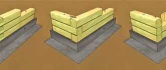
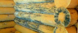
Knitting log corners
A variation of the cross-shaped connection is the method of fastening the beams together without any residue; in this case, the two sides of the cross-shaped connection have no continuation. This connection is used when laying corners and is called “no residue in the paw.” Cutting a castle without leaving any residue does not require the use of special tools; the construction of a log house using this method is popular among individual developers.
A more complex method of corner mounting is dovetail installation; a dovetail lock is a reliable but complex fastening. Marking and complex cutting of such a connection requires professional skills; the technology is widely used in the construction of low-rise economy class housing.
Notch / mortise connections
A notch, mortise or groove connection is called a corner or median connection, when the end of one part is attached to the layer and another part. It is based on a butt joint with an end cut made in the face. Used in frame (house frames) or box (cabinets) connections.
Types of jack/punch connections
The main types of notch joints are the t-notch in the dark/semi-dark (often this term is replaced by the term “flush/semi-dark”), which looks like a butt joint, but is stronger, the corner notch (corner connection) in the quarter and the corner notch in the dark/semi-dark. A corner notch into a rebate and a corner notch into a rebate with darkness/semi-darkness are made in the same way, but the rebate is made deeper - two-thirds of the material is selected.
Carrying out cutting
1. Mark a groove on the front side of the material. The distance between the two lines is equal to the thickness of the second part. Continue the lines to both edges.
2. Using a thickness gauge, mark the depth of the groove between the marking lines on the edges. The depth is usually made from one quarter to one third of the thickness of the part. Mark the waste portion of the material.
3. Use a C-shaped clamp to securely fasten the part. Saw the shoulders on the outgoing side of the marking lines to the required depth. If the groove is wide, make additional cuts in the waste to make it easier to remove the material with a chisel.
Saw close to the marking line on the waste side, making intermediate cuts with a wide groove.
4. Using a chisel on both sides, remove excess material and check that the bottom is even. You can use a primer to level the bottom.
Use a chisel to remove waste, working from both sides, and level the bottom of the groove.
5. Check the fit; if the part fits too tightly, it may need to be trimmed. Check for squareness.
6. The notch connection can be strengthened in one of the following ways or a combination of them:
- gluing and clamping until the glue sets;
- screwing with screws through the face of the outer part;
- nailing at an angle through the face of the outer part;
- Nailing obliquely across a corner.
The notch connection is quite strong
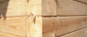
Advantages of cutting a warm corner
The advantages of this assembly method are so significant that they are worth mentioning separately.
- The assembly of the walls is so strong and dense that there is absolutely no need for additional strengthening of the joints.
- Due to the absence of seeping moisture, mold, rot and mildew will not form in the house, the corners will remain warm even in the most severe frosts.
- A building fixed in this way is so strong that it is not at all afraid of ground movements, earthquakes and other force influences. This indicates the high reliability and durability of the structure.
- The house looks nice both outside and inside.
- The design of a warm corner of a timber house is carried out without any fasteners, which significantly reduces construction costs and allows the design to be simplified to the maximum.
- The construction of the house occurs quite quickly due to the fact that the grooves on the timber are prepared in advance, at the sawmill.
Groove and side tongue joints
This is a combination of a quarter cut and a rebate cut. It is used in the manufacture of furniture and the installation of slopes for window openings.
Making a connection
1. Make the ends perpendicular to the longitudinal axes of both parts. Mark the shoulder on one part, measuring the thickness of the material from the end. Continue marking on both edges and the front side.
2. Mark the second shoulder from the end side; it should be at a distance of one third of the thickness of the material. Continue on both edges.
3. Using a thickness gauge, mark the depth of the groove (one-third of the thickness of the material) on the edges between the shoulder lines.
4. Using a hacksaw, saw through the shoulders to the thickness line. Remove waste with a chisel and check the alignment.
5. Using a thicknesser with the same setting, mark a line on the back side and on the edges of the second part.
Adviсe:
- Mortise and tongue-and-groove joints can be easily made using a router and a suitable guide - either for the groove only, or for both the groove and the tongue. Recommendations for proper operation of the router, see p. 35.
- If the comb fits into the groove too tightly, trim the face (smooth) side of the comb or sand it with sandpaper.
6. From the front side, use a thicknesser to mark the edges towards the end and at the end itself. Saw along the lines of the planer with a hacksaw. Don't cut too deep as this will weaken the joint.
7. Using a chisel from the end, remove the waste. Check fit and adjust if necessary.
Manufacturing technology
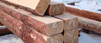
A house made of profiled timber is delivered to households in disassembled form. Installation of such a design does not provide for the collection of waste base material. The building is installed taking into account the design features and wood production technologies.
In its middle, the density is higher and contains a lot of resin (coniferous) or tannins (deciduous). Due to the absence of sap flow in the core of the trunk, the tree has high strength.
Often this product is given the following profile:
- the outer side is flat or semi-oval shaped;
- the inner side is straight;
- the lower and upper sides have tongues and grooves (used when installing a house).
The production process itself is carried out as follows. Pine edged timber is used as the starting material. It has high density and strength and contains virtually no moisture. Its cross-section must be rectangular, without deviations or cut lines. Material that is affected by fungus and insects is also not used.
Before profiling, the workpieces are kept for 3-5 months in warehouses or placed in special drying chambers. It is necessary to check the material for moisture. This figure should not exceed 22%.
Profiling is carried out on special machines with 4 sides, in which the number of spindles exceeds 6 pieces, and the minimum cross-section of the workpiece is 250x240 mm. The result is a finished product of a calculated shape or profiles with a smooth surface.
Half-tree connections
Half-timber joints are frame joints that are used to join parts together face to face or along an edge. The joint is made by removing the same amount of material from each piece so that they fit flush with each other.
Types of half-tree connections
There are six main types of half-timber joints: transverse, corner, flush, miter, dovetail and splice.
- Half-tree cross connection . Allows you to connect two intersecting parts without cutting one in half. It is performed in the same way as a notch connection with half the material removed from each part. The width corresponds to the width of the part being intersected. The material is removed from the bottom of one part and from the top of the second.
- Half-tree corner connection . Made for the end connection of two parts at an angle of 90°. A half-wood T-joint is similar to a corner joint, but a groove is selected on one part, and a rebate (overlay) on the second. It can be done in the dark.
- Half-tree miter joint . Used when a decorative overlay is made on the upper front side. The bevel of the face of the connection corresponds to the rotation of the cover plate.
- Half-tree dovetail connection . A dovetail-shaped tenon is cut out of this connection (on both or both sides). The connection is disconnected only if the upper part is lifted upward from the groove of the lower one. The slope is usually 1:6.
- Half-tree splicing. This connection is used to connect parts with their ends in one straight line using an overlay. The length of the selected part of the material (overlay) is equal to the width of the part. For sufficient strength, the connection requires
Joints in a poptree are similar to a notch/insetgain.
Making a half-tree corner connection
1. Align the ends of both parts. On the top side of one of the parts, draw a line perpendicular to the edges, stepping back from the end to the width of the second part. Repeat on the underside of the second piece.
2. Set the thicknesser to half the thickness of the parts and draw a line on the ends and edges of both parts. Mark the waste on the top side of one piece and the bottom side of the other piece.
3. Clamp the part in a vice at an angle of 45° (faces vertical). Saw carefully along the grain, close to the thickness line on the waste side, until the saw is diagonal. Turn the piece over and continue cutting carefully, gradually lifting the saw handle until the saw is aligned with the shoulder line on both edges.
4. Remove the part from the vice and place it on the surface. Press it tightly to the tsulaga and clamp it with a clamp.
5. Saw the shoulder to the previously made cut and remove the waste. Use a chisel to smooth out any unevenness in the sample. Check that the cut is neat.
6. Repeat the process on the second piece.
7. Check the fit of the parts and, if necessary, level them with a chisel. The connection must be rectangular, flush, without gaps or backlash.
8. The connection can be strengthened with nails, screws, and glue.
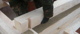
Marking beams for wall assembly
Practical construction experience shows that it is not realistic to keep in mind the sequence of marking the elements of corner joints.
Before starting work, draw a diagram of the assembly of the walls of the house, which indicates: the serial number of the crown, the type of connecting element at the ends of the blanks, the position of the openings in the wall.
The crown of the longitudinal wall consists of two parts: the main beam of a standard length of 6 meters and an extension of 3 meters. On one crown, long beams are laid on the left, and extensions on the right. On the next crown, installation begins in a similar order, but on the right.
The parts of the crown of the transverse wall and the partition are made from one beam of a standard length of 6 meters.
How to correctly and quickly mark tenons, grooves and other profiles and ensure identical dimensions of lumber blanks? The easiest way to do this is using templates. The template is placed on the beam and the outline of the template profiles is transferred to the surface of the beam with a marker.
It is more convenient, faster to mark and there will be fewer errors if the template completely follows the contour of the part and has the same length as the part being marked. I placed the template on the timber and immediately transferred all the dimensions and profiles to the workpiece.
How to mark parts with spikes? Obviously, the tenon and groove are elements of the same unit, which means they must match each other in size and location.
In a part with a tenon, a tenon is marked in place of the groove. If the dimensions of the groove are 5x5 cm, then the tenon should have dimensions of 4.5x4.5 cm. The gap is filled with inter-crown insulation.
The template profile is transferred to the upper edge of the beam. The markings are transferred to the vertical edge of the beam using a square. Accurate cuts are made using these markings.
Miter corner connections
Miter corner joints are made by bevelling the ends and hide the end grain and are aesthetically more consistent with the angular rotation of the decorative trim.
Types of miter corner joints
To bevel the ends in a miter joint, the angle at which the parts meet is divided in half. In a traditional connection, this angle is 90°, so each end is cut at 45°, but the angle can be either obtuse or acute. In uneven miter corner joints, parts with different widths are connected.
Performing miter joints
1. Mark the length of the pieces, keeping in mind that it should be measured along the long side, since the bevel will reduce the length inside the corner.
2. Having decided on the length, mark a line at 45° - on the edge or on the face, depending on where the bevel will be cut.
3. Using a combination square, transfer the markings to all sides of the part.
4. When cutting by hand, use a miter box and a hacksaw or hand miter saw. Press the piece firmly against the back of the miter box - if it moves, the bevel will be uneven and the joint will not fit well. If you are simply sawing by hand, watch the process so as not to deviate from the marking lines on all sides of the part. A power miter saw, if you have one, will make a very neat bevel.
5. Place the two pieces together and check the fit. You can correct it by trimming the bevel surface with a plane. Firmly fix the part and work with a sharp plane, setting the knife overhang to a small extent.
6. The connection should be nailed through both parts. To do this, first place the parts on the surface and drive nails into the outer side of the bevel so that their tips slightly appear from the bevels.
Place nails in both parts so that the tips protrude slightly from the surface of the bevel.
7. Apply glue and press the joint tightly so that one part protrudes slightly and overlaps the other. First, drive nails into the protruding part. Under the blows of the hammer when hammering nails, the part will move slightly. The surfaces must be level. Nail the other side of the joint and countersink the nail heads. Check for squareness.
Drive the nails into the protruding part first and the hammer will move the joint into position.
8. If due to unevenness of the workmanship there is a small gap, smooth the connection on both sides with the round blade of a screwdriver. This will move the fibers, which will close the gap. If the gap is too large, you will either have to redo the connection or seal the gap with putty.
9. To strengthen the corner joint, you can glue a wooden block inside the corner if it is not visible. If appearance is important, the connection can be made using a tenon or secured with veneer dowels. Dowels or lamellas (standard flat plug-in tenons) can be used inside flat joints.
Length extension
The length of industrially produced timber is determined by GOST 24454-80; of the many sizes of timber, 3- and 6-meter blanks are most in demand. When splicing, the ends of the joined beams are secured in various ways:
- Half-tree connection;
- On the root thorn;
- Straight patch lock;
- Oblique patch lock;
- Oblique cut.
The choice of fastening for the connected beams depends on the tasks at hand. For decking, a straight lock is used; for vertical supports, a half-tree or tenon lock is used; for the construction of 3D structures, oblique locks are used. Locks are reinforced with building brackets, dowels and dowels; bolted fastenings are used for load-bearing supports. In order to maintain the uniformity of the surface texture of the laminated veneer lumber, the length is increased using the toothed connection method or butt joints with a key, and the joints are reinforced with waterproof glue.
The longitudinal installation of timber roof rafters has its own characteristics - it is necessary to take into account the impact of multidirectional loads. For the connection, an oblique cut is used, reinforced with bolted fastening with a diameter of 10-12 mm.
Miter splicing and cutting connection
A miter splice connects the ends of parts that are located on the same straight line, and a rip splice is used when it is necessary to connect two profile parts at an angle to each other.
Miter splicing
When miter splicing, the parts are connected with identical bevels at the ends in such a way that the same thickness of the parts remains unchanged.
Connection with cutter
A connection with a cut (with a cut, with a fit) is used when it is necessary to connect two parts with a profile in a corner, for example, two plinths or cornices. If the part moves during the process of fastening it, the gap will be less noticeable than with a miter joint.
1. Secure the first baseboard in place. Move the second plinth located along the wall close to it.
Clamp the first baseboard in place and press the second baseboard against it, lining it up with the wall.
2. Run a small wooden block with a pencil pressed to it along the profile surface of the fixed baseboard. The pencil will leave a marking line on the plinth being marked.
Using a block with a pencil pressed to it, with the tip pointed at the second plinth, draw along the relief of the first plinth, and the pencil will mark the cut line.
3. Cut along the marking line. Check the fit and adjust if necessary.
Complex profiles
Place the first plinth in place and, placing the second plinth in the miter box, make a bevel on it. The line formed by the profile side and the bevel will show the required shape. Cut along this line with a jigsaw.
How to fasten timber together
In addition to corners and longitudinal joining, the crowns have to be connected to each other in the vertical direction. After laying two rows of timber, additional fastening in the form of dowels or dowels must be installed.
To tie the crowns, it is best to use square wooden rods with an edge size of 18 mm and a length of 250 mm. For installation, pre-drill 25 mm holes. The drilling depth is equal to one and a half heights of the timber. That is, one dowel completely pierces the upper beam and half of the lower one. The dowels are driven in a checkerboard pattern so that the vertical fastening line does not coincide with the connections on the lower rows. Dowels must be attached to corners, window and door openings.
Lug connections
Lug joints are used when there is a need to connect intersecting parts located “On Edge”, either at the corner or in the middle (for example, the corner of a window sash or where a table leg meets a crossbar).
Types of lug connections
The most common types of eyelet connections are corner and T-shaped (T-shaped). For strength, the connection must be glued, but it can be strengthened with a dowel.
Making an eyelet connection
1. Make the markings in the same way as for a tenon-to-socket joint, but divide the thickness of the material by three to determine one-third. Mark the waste on both parts. On one part you will need to select the middle. This groove is called an eye. On the second part, both side parts of the material are removed, and the remaining middle part is called a tenon.
2. Saw along the grain to the shoulder line along the marking lines on the waste side. Use a hacksaw to cut out the shoulders, and you will get a tenon.
3. Working from both sides, remove material from the eye with a chisel/mortise chisel or jigsaw.
4. Check the fit and adjust with a chisel if necessary. Apply glue to the joint surfaces. Check for squareness. Using a C-clamp, clamp the joint while the glue hardens.
Tenon to socket connection
Tenon-to-socket joints, or simply tenon joints, are used when two parts are joined at an angle or intersection. It is probably the strongest of all frame joints in joinery and is used in the making of doors, window frames and furniture.
Types of tenon-to-socket connections
The two main types of tenon joints are the usual tenon-to-socket joint and the stepped tenon-to-socket joint (semi-dark). The tenon and socket make up approximately two-thirds of the width of the material. The socket is widened on one side of the groove (semi-dark), and a tenon step is inserted into it from its corresponding side. Semi-darkness helps prevent the thorn from being turned out of the socket.
Conventional tenon-to-socket connection
1. Determine the joint position on both pieces and mark all sides of the material. The marking shows the width of the intersecting part. The tenon will be at the end of the crossbar, and the socket will go through the post. The tenon should have a small allowance in length for further stripping of the joint.
2. Select a chisel that is as close in size as possible to a third of the thickness of the material. Set the thicknesser to the size of the chisel and mark the socket in the middle of the post between the previously marked marking lines. Work from the front side. If desired, you can set the thicknesser solution to a third of the thickness of the material and work with it on both sides.
H. In the same way, mark the tenon on the end and both sides until you mark the shoulders on the crossbar.
4. In a vice, clamp an auxiliary support in the form of a piece of wood high enough so that you can attach the stand to it, turned “on edge.” Secure the stand to the support, placing the clamp next to the marking of the socket.
5. Cut out a nest with a chisel, making an allowance inwards of about 3 mm from each end so as not to damage the edges when removing waste. Hold the chisel level, keeping its edge parallel to the plane of the counter. Make the first cut strictly vertically, placing the sharpening bevel towards the middle of the socket. Repeat from the other end.
6. Make several intermediate cuts, holding the chisel at a slight angle and with the sharpening bevel down. Select a retreat, using the chisel as a lever. Having gone deeper by 5 mm, make more cuts and select a waste. Continue until about halfway thick. Turn the piece over and work the same way on the other side.
7. After removing the main part of the waste, clean out the nest and cut off the previously left allowance to the marking lines on each side.
8. Cut a tenon along the fibers, running a hacksaw along the marking line on the waste side, and cut out the shoulders.
9. Check fit and adjust if necessary. The shoulders of the tenon should fit neatly into the post, the connection should be perpendicular and have no play.
10. To secure, you can insert wedges on both sides of the tenon. The gap for this is made in the socket. Working with a chisel from the outside of the socket, widen it to about two-thirds of the depth with a 1:8 slope. The wedges are made with the same bias.
11. Apply glue and squeeze tightly. Check for squareness. Apply glue to the wedges and drive them into place. Saw off the tenon allowance and remove excess glue.
Other tenon joints
Tenon joints for window frames and doors are somewhat different from tenon joints in semi-darkness, although the technique is the same. Inside there is a fold and/or lining for glass or panel (panel). When making a tenon-to-socket connection on a part with a rebate, make the plane of the tenon in line with the edge of the rebate. One of the shoulders of the crossbar is made longer (to the depth of the fold), and the second is made shorter so as not to block the fold.
Tenon joints for parts with overlays have a shoulder that is cut to match the profile of the overlay. An alternative is to remove the trim from the edge of the socket and make a bevel or cut to match the mating piece. Other types of tenon-to-socket connections:
- Side tenon - in the manufacture of doors.
- A hidden beveled tenon in semi-darkness (with a beveled step) - to hide the tenon.
- A tenon in the dark (tenon steps on both sides) - for relatively wide parts, such as the bottom trim (bar) of a door.
All these connections can be through, or they can be blind, when the end of the tenon is not visible from the back of the rack. They can be strengthened with wedges or dowels.
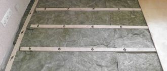
DIY installation: step-by-step instructions
Schemes of rigid fastening of timber.
First of all, you need to make markup, which will be the basis for creating the project. This is done so that you can determine the level of the wall surface.
Next, you should measure the pitches of the fasteners. The distance in this case ranges up to 60 cm (the minimum gap is 30 cm). It is determined by the quality of the timber and its thickness.
The next step is strapping. To do this, lay the elements strictly along the contour of the wall being leveled. If you are planning to level one wall, then you need to attach the beam to the walls that are perpendicular. The use of pads is not required during installation.
It is recommended to first make a small hole in the part to be installed. This must be done so that the screws can be inserted. Remember that the diameter of the drilled hole should be slightly larger than the diameter of the screw.
Then you take the product and apply it to the surface of the wall. You do part of this work with a hammer and nail. Your task is to transfer the mark for the hole to the surface.
The next stage of work is to drill the planned holes. As a rule, you must drive wooden chops or regular dowels into them.
Next, you install the wooden block in its place, securing it with a screw. However, you can use another method: the timber is attached to the chop with a nail, using a hammer.
Scheme of fastening the timber to each other.
Now you attach and install all additional contour elements. For convenience, you should stretch a thread between them. What is the thread for? Using it you will be able to determine the height of the block, and in all places where the beam is attached to the wall. This way you measure the distance that forms from the surface of the wall to the thread. Then we subtract the height of the element from this distance.
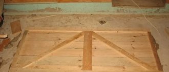
Then you should take pieces of plywood of various thicknesses and build a structure. During the work you will need an ax and a chisel.
Once the block is ready, you can start drilling a hole in it. The diameter of the hole made must be larger than the diameter of the screw.
Next, you should make holes in the beam so that you can later attach it to the wall. How to drill a hole depends on the height of the element, as well as the material from which it is made. For example, if the beam has a height of more than 6 cm, and the material is larch, then you need to use a drill with a drill with a diameter of 12 mm
When installing, take into account one important circumstance: the head of the screw must be completely inserted into the beam, do not allow any elevations, try to place the screw in the inner part of the element
If the timber is of considerable thickness, then you should make holes up to 3 cm deep. Then we proceed to fasten the element to the surface using previously made blocks.
To make sure that the fixed timber is level, use a building level. If it turns out that the beam is attached to the surface a little higher than planned, then unscrew the screw and replace the head. You can also use the second method: unscrew the screw (just not all the way) and place spacers of the required parameters on both sides of the element.
If the beam is located below the planned level, unscrew the screw and change the head. However, if the difference in marks is insignificant (up to 2 mm), you can plan off the unnecessary part using a construction plane.
Rally
Wide, high quality timber is becoming increasingly difficult to find and very expensive. In addition, such wide boards are subject to very large shrinkage deformations, which makes working with them difficult. To join narrow boards along the edges into wide panels for tabletops or workbench covers, they use bonding.
Preparation
Before starting the bonding itself, you must do the following:
- If possible, select radial sawn boards. They are less susceptible to shrinkage deformations than tangential sawn timber. If tangentially sawn boards are used, then place their core side alternately in one direction and the other.
- Try not to combine materials with different sawing methods into one panel.
- Never join boards of different types of wood unless they have been properly dried. They will shrink and crack differently.
- If possible, place the boards with the grain in the same direction.
- Be sure to cut the material to size before joining.
- Use only good quality glue.
- If the wood will be polished, select the texture or color.
Rallying on a smooth fugue
1. Lay out all the boards face up. To facilitate subsequent assembly, mark the edges with a continuous pencil line drawn along the joints at an angle.
2. Plane straight edges and check fit to appropriate adjacent boards. Align the ends or pencil lines each time.
3. Make sure there are no gaps and that the entire surface is flat. If you squeeze the gap with a clamp or fill it with putty, the connection will subsequently crack.
4. When planing short pieces, clamp two in a vise, right sides together, and plane both edges at the same time. There is no need to maintain the squareness of the edges, since when joining they will mutually compensate for their possible tilt.
5. Prepare as for a butt joint and apply glue. Using squeezing and rubbing, connect the two surfaces, squeezing out excess glue and helping the surfaces “suck” to each other.
Other ways to rally
Other bonding connections with different strengths are prepared in the same way. These include:
- with dowels (dowels);
- in tongue and groove;
- at a quarter.
Adviсe
If you need to make small workpieces, for example, for repairing some furniture, a wall shelf, a drawer, a kitchen countertop, when it is not possible to make grooves or quarters, then you can glue it onto a smooth truck. And here you may need a set with center markers. This is a relatively inexpensive thing, but a very good assistant.
If your task is to assemble several dozen boards so that the panel looks like a single whole, then you should not use wide blanks for this. Because wide pieces can become deformed when the humidity of the environment changes and this will be very noticeable.
Note: The finished laminated veneer lumber will not deform if everything is done correctly. But maybe. This can be avoided by changing the direction of the annual rings on the bars across the entire width. If, of course, you take a straight board without a flaw, then the process will be much easier.
Gluing must be done so that the joints along the length are almost invisible.
Gluing and fixing with clamps
Gluing and fixing glued parts is an important part of woodworking, without which many products will lose strength.
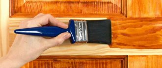
Adhesives
The glue strengthens the connection, holding the parts together so that they cannot be easily pulled apart. When working with adhesives, be sure to wear protective gloves and follow the safety instructions on the packaging. Clean the product from excess glue before it sets, as it can dull the plane knife and clog the abrasive sandpaper.
PVA (polyvinyl acetate)
PVA glue is a universal wood glue. While still wet, it can be wiped off with a cloth dampened with water. It perfectly glues loose surfaces, does not require long-term fixation for setting and sets in about an hour. PVA gives a fairly strong connection and sticks to almost any porous surface. Provides a permanent connection but is not heat or moisture resistant. Apply with a brush, or for large surfaces, dilute with water and apply with a paint roller. Since PVA glue is water-based, it shrinks when it sets.
Contact glue
Contact adhesive bonds immediately after application and joining of parts. Apply it to both surfaces and when the glue is dry to the touch, press them together. It is used for laminate or veneer to chipboard. No fixation required. Can be cleaned with solvent. Contact adhesive is flammable. Handle it in a well-ventilated area to reduce fumes. Not recommended for outdoor use as it is not moisture or heat resistant.
Epoxy adhesive
Epoxy glue is the strongest of the adhesives used in woodworking, and the most expensive. This is a two-component resin-based adhesive that does not shrink when set and softens when heated and does not creep under load. It is water-resistant and bonds to almost all materials, both porous and smooth, with the exception of thermoplastics, such as polyvinyl chloride (PVC) or plexiglass (plexiglass). Suitable for outdoor use. In an uncured form, it can be removed with a solvent.
Hot melt adhesive
Hot melt, solventless adhesive will stick to almost anything, including many plastics. Typically sold in the form of glue sticks that are inserted into a special electric glue gun. Apply glue, connect the surfaces and compress for 30 seconds. No fixation required. Can be cleaned with solvents.
Fixation clips
Clamps come in a variety of designs and sizes, most of which are called clamps, but usually only a couple of varieties are needed. Be sure to place a piece of scrap wood between the clamp and the work to avoid indentations from the applied pressure.
Gluing and fixation technique
Before gluing, be sure to assemble the product “dry” - without glue. Secure as necessary to check connections and dimensions. If everything is fine, disassemble the product, arranging the parts in a convenient order. Mark the areas to be glued and prepare clamps with jaws/stops set at the required distance.
Frame assembly
Using a brush, spread the glue evenly onto all surfaces to be glued and quickly assemble the product. Remove excess glue and secure the assembly with clamps. Apply even pressure to compress the joints. The clamps must be perpendicular and parallel to the surfaces of the product.
Place the clamps as close to the connection as possible. Check the parallelism of the crossbars and align if necessary. Measure the diagonals - if they are the same, then the rectangularity of the product is maintained. If not, then a light but sharp blow to one end of the post can straighten the shape. Adjust the clamps if necessary.
If the frame does not lie flat on a flat surface, tap the protruding areas with a mallet through a block of wood as a spacer. If this does not help, you may need to loosen the clamps or use clamps to secure a block of wood across the frame.
Panel assembly (joining)
Using a brush, apply glue evenly to both edges. Place clamps at each end and, if necessary, between them at intervals of no more than 30 mm. Check the alignment of the ends and the coincidence of the pencil marks. Use the clamps to apply slight pressure. The clamp on top will equalize the pressure and help prevent warping. Tighten the clamps evenly. Remove excess glue and allow the joints to cure. Make sure the surface is smooth and there are no protrusions or bends.
Joints of wooden parts: 11 types of joints of wood
wood glue connections